Thermocouple Schematic Diagram Thermocouple Working Principl
Understand the thermocouple circuit working principle and its Uncategorized archives Temperature measurements with thermocouples ~ learning instrumentation
Thermocouple Schematic Diagram
Thermocouple diagram, circuit, construction, applications Thermocouple work does working diy type sensor types its temperature measure which consists Thermocouple diagram, circuit, construction, applications
Thermocouple types, junctions, connector and tip styles
Thermocouple-working,types-e,j,k,t,s,r,grounding,thermopile,advantages(a) schematic diagram of the experimental setup, (b) thermocouple Thermopile thermocouple thermocouples thermopilesThermocouple schematic diagram.
Explanation of thermocouple with circuitThermocouple working principle explained types of thermocouple Thermocouple schematic diagramThermocouple: what is it? how does it work? types of.

Thermocouple types, junctions, connector and tip styles
What is a thermocouple and how does it work?Working thermocouple principle temperature thermocouples sensor work cold used omega diagram do voltage engineering probe principles response Thermocouple figureThermocouple circuit junction measuring seebeck heat mot forskjellige lyden hverandre betydning metaller termokopel effect instrument.
Schematic diagram of a thermocoupleThermocouple temperature instrument connection junction sensor schematic thermocouples basic cold control diagram measurement wire measuring sensors electrical engineering simple wires Thermocouple wiring schematicThermocouple and thermopile – hvac basics.

Thermocouple experimental evaporator
Thermocouple principleThermocouple : working principle and its applications Thermocouple diagram igcseThermocouple schematic diagram.
Thermocouple circuit working diagram principle its applications definitionThermocouple circuit construction simple figure What is a thermocouple? comark instruments breaks it down for youThermocouple measurement junctions thermocouples cable wires indicator joining.

Thermocouple circuit basic control explanation
Thermocouple complete guide with arduino interfacingThermocouple signal conditioning: challenges and solutions Thermocouple constructionThermocouple schematic.
Figure 1-4. typical thermocouple circuitsBlock diagram of the thermocouple conditioning circuit. A typical circuit diagram of a thermocoupleThermocouple principle.

How does a thermocouple work? working principle and operation.
Thermocouple diagram signal conditioning challenges solutions simplified figure1Thermocouple schematic diagram Thermocouple control thermocouples indicator junctions styles wiresThermocouple measurement thermopile working.
Thermocouple schematicThermocouple circuit diagram Thermocouple temperature junctions tip meter connector thermocouples j2 j1 wiresThermocouple types, junctions, connector and tip styles.


Thermocouple Schematic

Understand the Thermocouple Circuit Working Principle and Its

Uncategorized Archives - Electrical & Automation Solutions

Thermocouple Construction - Inst Tools

Figure 1-4. Typical thermocouple circuits

Thermocouple Schematic Diagram - Circuit Diagram
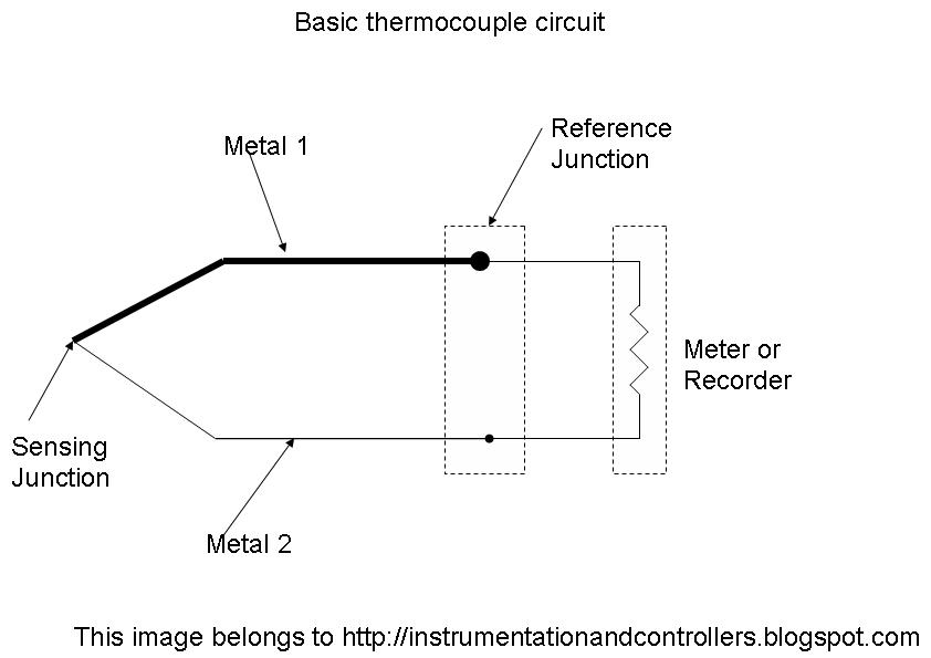
Explanation of Thermocouple with Circuit - Instrumentation and Control